Cover Plates
Features
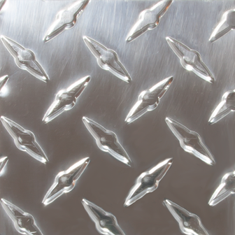
- Aluminum tread plates are available in thicknesses of 1/4″ and 3/8″ in alloy 6061-T6 and in a thickness of 1/4″ in alloy 5086-H116
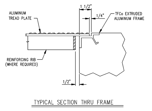
- The embedded frames are aluminum extrusions of alloy 6063-T6.
- Continuous anchor reduces fabrication cost and delivery time.
- The portion of the frames in contact with concrete are painted with bitumastic
Options
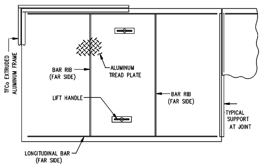
- Custom designed reinforcing
- Lift handles
- Gaskets
- Bolted down covers

Drawings

Cover Plate

Floor Plates Plan
Specifications
1) Aluminum checkered floor plates shall be a minimum of 1/4″ thick and shall be alloy 6061-T6 or 5086-H112.
2) Floor plates shall be designed to support a uniform load of 200 pounds per square foot with a maximum deflection of 1/4″. The maximum fiber stress shall not exceed that which is allowed by the Aluminum Association.
3) The fabricator shall submit calculations to the Engineer along with the submittal drawings. Submittal data will be in enough detail to determine if reinforcing ribs are required and if required, determine rib size, spacing and welding pattern.
4) Paint all aluminum surfaces in contact with concrete or dissimilar metals with a shop coat of bituminous paint.
